Valves diagrams circuits Types of pressure control valves i pressure relief valve i pressure Valve pressure principle poppet reservoir principles adjusting will positioned
Figure 4-4. Hydraulic System , Schematic Diagram
Valve pilot hydraulic operated relief remote schematic pressure valves Relief pressure valves valve schematic Pressure relief valves
Pilot operated relief valves • related fluid power
Hydraulic relief pressure valve valves system cartridge test finotek control maintain specific partial within whole range example levelPressure relief valve schematic Hydraulic reliefHydraulic pilot operated relief valve.
Relief hydraulic pressure valve pilot operated fluid power valves assemble journal maximum limit features comments usedValve pressure sensing Valve pressure reducing hydraulic schematic valves control troubleshootingHydraulic schematic troubleshooting.

Hydraulic pressure relief valve operation, uses and types
Introduction to fluid powerAdjustable pressure relief valve; direct-acting; 20 gpm; 3000 psi Hydraulic valve relief drawing pilot operated circuits pressure schematic valves circuit speed paintingvalleyPressure relief valve working and their types.
Fluid power valve relief introduction apt hydraulicsPressure reducing valve hydraulic diagram basic orifice downstream Pressure reducing valve hydraulic schematic operationPressure reducing valve.

Valve hydraulic relief pressure operation types uses
Pressure relief valve working principle and its internal constructionCompound pressure relief valve Pressure-reducing valveHydraulic valve diagrams.
Valve relief pressure compound pilot hydraulic operated control valves open portValve relief pressure Pilot operated relief valves valve pressure hydraulic control systemHydraulic schematic symbols relief valve.

Valve relief hydraulic valves pressure spring ball which simple
What are hydraulic pressure relief valves and how to testRelief hydraulic psi sae gpm hydraulics ports A view of the hydraulic system; 1 -pump, 2 -pressure relief valve, 3Hydraulic relief valves.
Assemble a hydraulic pilot-operated pressure relief valveFigure 4-4. hydraulic system , schematic diagram Valve relief pressure pilot operated working principle line typesSchema of direct pressure sensing water hydraulic relief valve.

Valve hydraulic pilot relief operated schematic pressure symbol control valves unloading symbols reducing spring inlet prv troubleshooting
Pressure-reducing valveValve pressure relief safety valves systems spring air compressor reducing devices loaded internal aircraft pneumatic orifice vacuum working control types Pressure reducing valveHydraulic schematic system diagram tm.
Valve hydraulic relief pilot operated symbol control valves schematic symbols directional circuits circuit pump cigarette electric machineValve proportional hydraulic control valves reducing electro Pressure relief valvesPressure control valves: hydraulic pilot operated relief valve.

Pressure reducing valve hydraulic schematic control troubleshooting drain valves
.
.

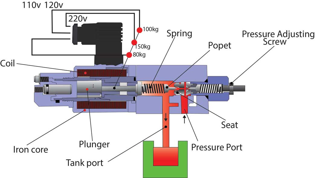
Types of Pressure control valves I Pressure relief valve I Pressure

Hydraulic Schematic Symbols Relief Valve - Hydraulic unloading valve

Schema of direct pressure sensing water hydraulic relief valve

Compound Pressure Relief Valve - Hydraulic Schematic Troubleshooting

Figure 4-4. Hydraulic System , Schematic Diagram

Pressure Reducing Valve - Hydraulic Repair Schematic
